
If you buy something through our links, ToolGuyd might earn an affiliate commission.
I have been sourcing parts for a CNC conversion build, and as part of that process involves learning how to properly switch and control higher power loads.
It’s been an interesting but very slow process.
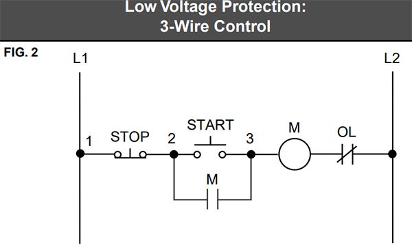
Shown above is a 3-wire control circuit, provided in reference materials by Schneider Electric (PDF). The diagram is easy to understand, but it took a very long time to find.
I also found one YouTube video particularly helpful:
Before getting there, I found so many bad videos and countless websites that seem to have copy/pasted the same information from each other.
Here’s how each research step has gone:
Step 1: Figure out what I need to learn – usually by figuratively stumbling over an obstacle.
Step 2: Find an example of how it’s done.
Step 3: Find explanations of why things are done that way.
Step 4: Determine what I will need for my build and future projects.
Teknic, the company whose motors I purchased for my build, provided an example of a safety stop control solution:

The parts list they provided has specific recommendations, and I’ll be straying from it a little bit.
I don’t really need to completely design something new for my CNC control panel build, as there are a couple of other examples I could also copy and adapt without too much difficulty.
But I’m the type that feels compelled to understand why certain components are chosen, and why things are done in a certain way.
Is it crucial for my current build? Probably not. But I have others in mind where there could be greater consequences if I get something wrong.

Every step turns into a huge rabbit hole.
Shown here is an example of how an Omron safety relay can be put to use with E-stops and interlock switches.
Others are a little easier to read.
Once I find a good explanation, everything falls into place.
For my build:
Basic: 2 momentary switches and E-stop(s) can control a contactor for powering a load on and off.
Better: 3 momentary switches, E-Stop(s), and a safety relay can read and control a contactor for powering a load.
Best: 3 momentary switches, E-Stop(s), safety relay, and (2) contactors can power a load.
Safety contactors are ideal, but could be overdoing it. Even a safety relay might be overdoing it, but seems to be the proper way to do things.
The costs quickly balloon out of control, and so it’s also a matter of understanding and assessing risks.
A safety contactor has linked switches so that if a normally-open switch fails in the closed state (welds shut), a normally-closed switch cannot close. It seems that for my needs I can achieve similar with a general contactor and linked auxiliary contact. Maybe.